
Instrument's Characteristics
In this page are listed the main characteristics of the imaging mode and the filters of the instrument.
This is intended as a quick reference. A detailed description of HAWK-I can be found in the user's manual
GRAAL+HAWK-I GLAO mode
In P102 HAWK-I started to offer the Ground Layer Adaptive Optic (GLAO) mode of the VLT Adaptive Optics Facility (AOF) via the GRAAL adaptive optics module, offering an AO corrected 7.5'x7.5' field of view. GRAAL is a module of the Adaptive Optics Facility (AOF) at UT4. GRAAL uses the 4 LGS system and the deformable secondary mirror to correct the turbulent atmospheric at ground layer for HAWK-I. The GRAAL+HAWK-I GLAO is operated in the Tip-Tilt free mode.

GRAAL focal plane illustration. The 4LGS rotate with respect to the FoV and the lasers are side-launched.
GRAAL GLAO Performance
The GRAAL GLAO performance depends on the ratio of the turbulence in the ground layer, also known as the ground layer fraction (GLF). At the GLF of 70%, GRAAL can improve a factor of 1.5 on the FWHM. Please find the following plot on the FWHM gain in Ks-band.
 |
FWHM gain in Ks-band in function of the DIMM seeing and the ground layer fraction measured in TTS-free mode.
To achieve the expected image quality for the science goal, the user should refer to the ETC to find out the turbulence category to request to reach the required performance.
Imaging mode: characteristics and sensitivity
The detectors
 HAWK-I Detectors definition HAWK-I Detectors definition |
|
*: The RON depends on the number of non-destructive samples during the integration.
DCR (Double-Correlated Read) refers to two samples, i.e. minimum DIT ~ 1.25s.
NDR (Non-Destructive Read) refers to > 10 samples, i.e. DIT > 10s
The gap
There is a small mis-alignment between the detectors. Quadrants 2,3 & 4 are tilted with respect to quadrant 1 by 0.13, 0.04 & 0.03degrees respectively.
Details of the gap between detectors
List of filters offered for HAWK-I
|
Plot of filters efficiency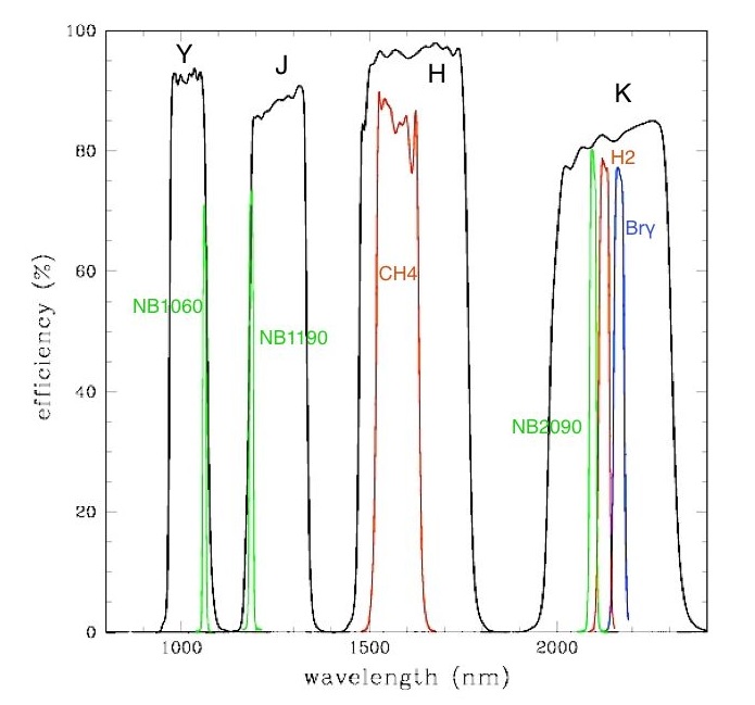 |