
Instrument Description and Performance
Instrument Description
ESPRESSO is the first instrument of a new VLT facility that can host instrumentation at the so-called Incoherent Combined Coudé Focus (ICCF). As such, in order to describe the instrument, one needs to understand the three components through which the light travels from the telescope to the detectors. These are: the UT Coudé Trains, the Front Ends, and the Spectrograph itself. Each of these components are described below. For a more detailed description, we point the interested reader to the ESPRESSO user manual.
The Coudé Trains
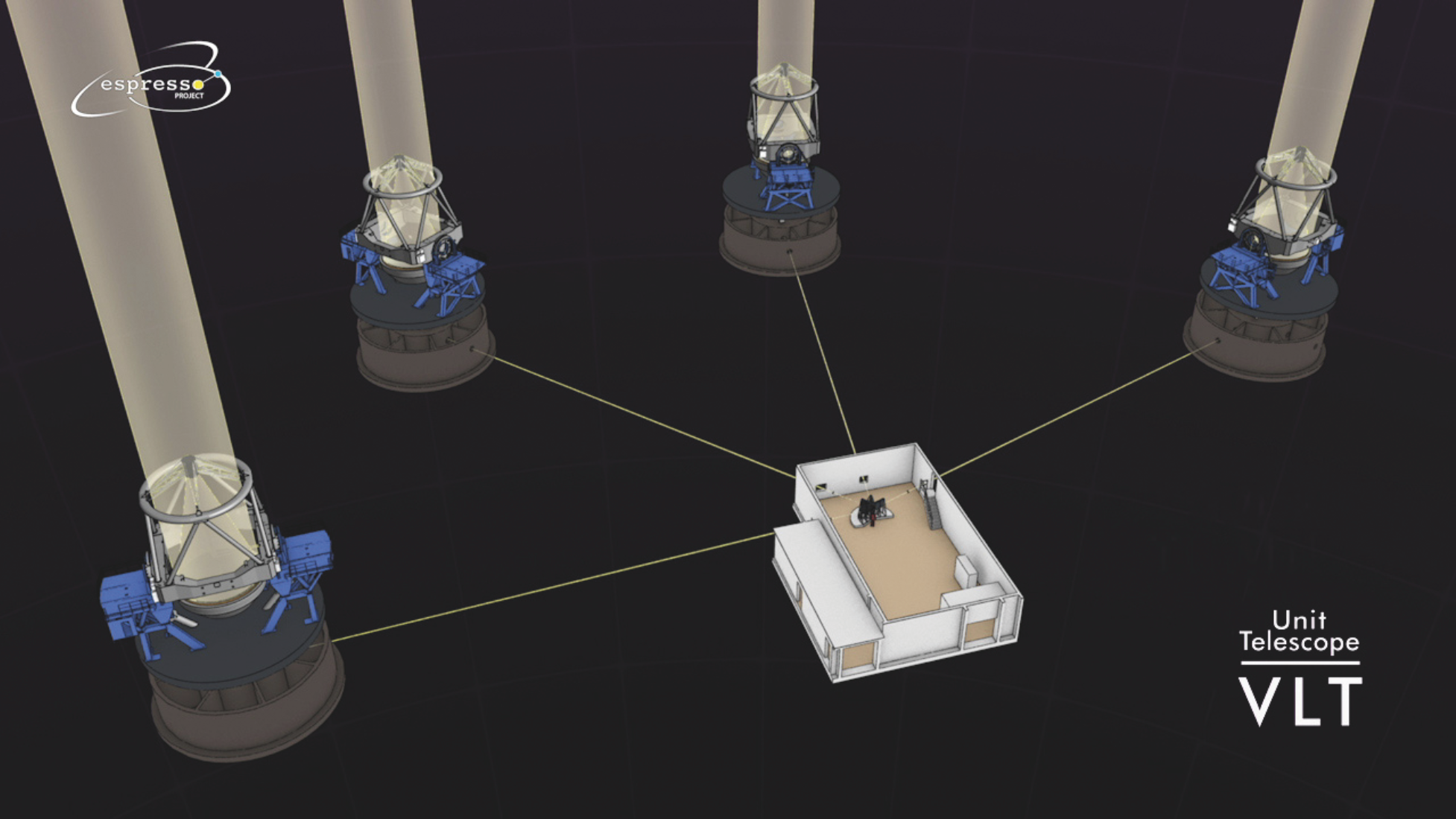 Distances between each UT and the Combined Coudé Laboratory (CCL) range between 48 m for UT2 and 69 m for UT1. A trade-off analysis between solutions based on mirrors, prisms, lenses, and fibres, points towards a full-optics solution. The chosen design with the position of the 11 optical elements is shown below in the second figure. The Coudé train picks up the light through a prism at the level of the Nasmyth-B platform and routes the beam through the UT mechanical structure down to the UT Coudé room, and farther to the CCL along the existing incoherent light ducts. The four trains relay a field of 17 arcsec around the acquired object to the CCL. The selected concept to convey the light of the telescope from the Nasmyth-B focus to the entrance of the tunnel in the Coudé room (CR) below each UT is based on a set of 6 prisms (with some power). The light is directed from the UT’s Coudé room towards the CCL using 2 large lenses. The beams from the four UTs meet in the CCL, where mode selection and beam conditioning is performed by the fore-optics of the Front-End sub-system.
The Front Ends
The Front-End transports the beam received from the Coudé, once corrected for atmospheric dispersion by the ADC, to the common focal plane where the pickups for the spectrograph fiber feeds are located. While performing such a beam conditioning, the Front-End can apply pupil and field stabilizations. These are achieved via two independent control loops each composed of a technical camera and a tip-tilt stage. Another dedicated stage delivers a focusing function. In addition, the Front-End handles the injection of the calibration light, prepared in the Calibration Unit, into the fibers and then into the spectrograph. As calibration sources, ESPRESSO is equiped with a laser frequency comb (LFC), two ThAr lamps (one for simultaneous reference and one for calibration) and a calibration light is foreseen to be composed of two ThAr, one for simultaneous Fabry-Pérot calibration. A toggling mechanism handles the selection between the possible observing modes in a passive way.

The Fibre-Link sub-system relays the light from the Front-End to the spectrograph and forms the spectrograph pseudo-slit inside the vacuum vessel. The 1-UT mode uses a bundle of 2 octagonal fibres each, one for the object and one for the sky or simultaneous reference. In the high-resolution (singleHR) mode, the fibre has a core of 140 μm, equivalent to 1 arcsec on the sky; in the ultra-high resolution (singleUHR) mode, the fibre core is 70 μm and the covered field of view is 0.5 arcsec. The fibre entrances are organized in pickup heads that are moved to the focal plane of the Front End when the specific bundle of the specific mode is selected. In the 4-UT mode (multiMR), four object fibres and four sky/reference fibres are fed simultaneously by the four telescopes. The four object fibres will finally feed a single square 280 μm object fibre, while the four sky/reference fibres will feed a single square 280 μm sky/reference fibre. In the 4-UT mode, the spectrograph will see a pseudo slit of four fibre images, although they will be square and twice as wide as the 1-UT fibres. Another essential task performed by the Fibre-link sub-system is the light scrambling. The use of a double-scrambling optical system will ensure both scrambling of the near field and far field of the light beam. A high scrambling gain, which is crucial to obtain the required RV precision in the 1-UT mode is achieved by the use of octagonal fibres (Chazelas et al. 2011).
The Spectrograph
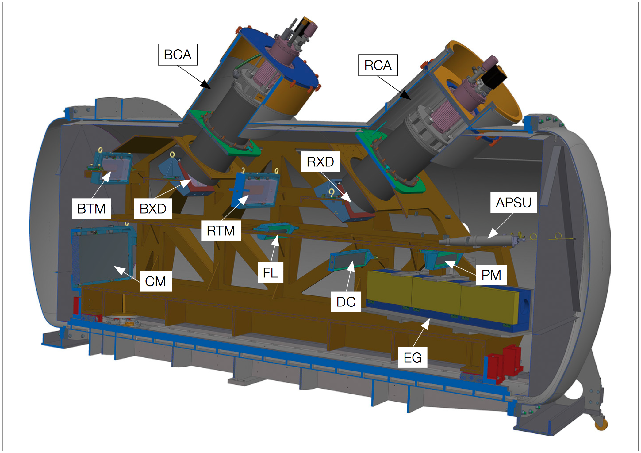
The spectrograph optics are mounted in a 3-dimensional optical bench specifically designed to keep the optical system within the thermo-mechanical tolerances required for high-precision radial velocity measurements. The bench is mounted in a vacuum vessel in which 10−5 mbar class vacuum is maintained during the entire duty cycle of the instrument. The temperature at the level of the optical system is required to be stable at the mK level in order to avoid both short-term drift and long-term mechanical instabilities. Such an ambitious requirement is obtained by locating the spectrograph in a multi-shell active thermal enclosure system. Each shell improves the temperature stability by a factor of 10, thus getting from typically Kelvin-level variations in the CCL down to 1 mK stability inside the vacuum vessel and on the optical bench.
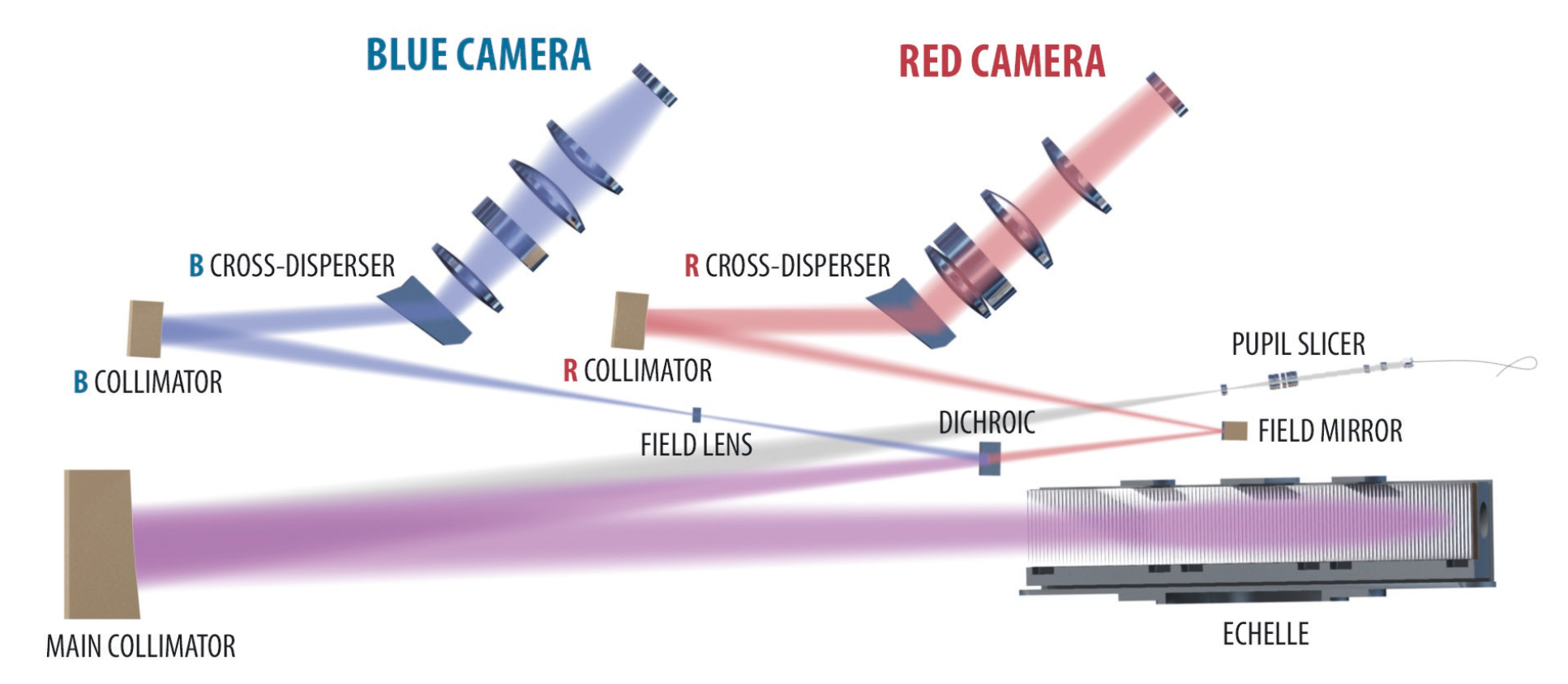
At the entrance of the spectrograph, an anamorphic pupil slicing unit (APSU) shapes the beam in order to compress the beam in cross-dispersion direction but not in main-dispersion direction, where high resolving power needs to be achieved. In the latter direction, however, the pupil is sliced and superimposed on the echelle grating to minimize its size. The rectangular white-pupil is then re-imaged and compressed by the anamorphic VPH grism. Given the wide spectral range and the required efficiency, two large 90x90 mm CCD detectors are required to record the full spectrum. Therefore, a dichroic beam splitter separates the beam in a blue and a red channel which in turn allows to optimize each spectroscopic arm for image quality and optical efficiency. The cross-disperser has the function of separating the dispersed spectrum in all its spectral orders. In addition, an anamorphism is re-introduced to make the pupil square and to compress the order width in cross-dispersion direction, such that the inter-order space is maximized.
Observing modes
The instrument can be operated in three observing modes: High Resolution 1-UT (HR), Ultra High-Resolution 1-UT (UHR), and Medium Resolution 4-UT (MR). The HR and MR modes allows the user to select different combinations of binning (1x1, 2x1, 4x2, and 8x4) and roeadout speed (SLOW and FAST) as a function of the S/N. For low S/N (10 or lower) FAST1x1 should be avoided, as this mode introduces a large readout error and a noticeable electronic noise pattern. For details please refer to the latest version of the ESO User Manual.
The main characteristics of the corresponding five instrument configurations are summarised below:
|
Purpose | Detector readout mode | CCD pixel binning (spat. x spec.) |
Combined readout, transfer & wiping time | RON (Blue detector) |
RON (Red detector) |
CONAD |
| SINGLE_HR11 | Spectroscopy and RV monitoring of bright targets (V<10-12) with 1 UT | FAST | 1x1 | 45 s | 8 e-/pix | 5 e-/pix | 1.1 e-/ADU |
| SINGLE_UHR11 | Very high-resolution spectroscopy with 1 UT | FAST | 1x1 | 45 s | 8 e-/pix | 5 e-/pix | 1.1 e-/ADU |
| SINGLE_HR21 | Spectroscopy and RV monitoring of fainter targets (V>10-12) with 1 UT | SLOW | 2x1 | 68 s | 3 e-/pix | 2 e-/pix | 1.1 e-/ADU |
| MULTI_MR42 [offered starting in P103] | Spectroscopy of faint targets with 4 UTs | SLOW | 4x2 | 41 s | 3 e-/pix | 2 e-/pix | 1.1 e-/ADU |
| MULTI_MR84 [offered starting in P103] | Spectroscopy of very faint targets with 4 UTs | SLOW | 8x4 | 36 s | 3 e-/pix | 2 e-/pix | 1.1 e-/ADU |
Instrument Performance
In this section, we will present a summary of the performance of the instrument after the commissioning runs and technical missions that took place between November 2017 and July 2019. Tthe latest intervention on the instrument aimed at increasing the transmission of the spectrograph, with particular attention on blue wavelengths.