
The triangulation sensor
A triangulation sensor projects a bright spot onto the surface by focusing a laser onto the surface,producing an easily detectable feature on the surface. A lens images the spot on the surface ontoa linear CCD and the centroid of the spot on the linear CCD is determined. There is a relationship between the distance of the triangulation sensor to the surface and the position of the image ofthe projected spot on the linear CCD.
| The schematic diagram of a triangulation sensor is shown on the right.Some triangulation sensors allow operation in such a way that specular and diffuse reflecting surfaces can be measured. Triangulation sensor used for measuring the distance to a surface with specular reflection. The laser spot on the surface of the sample at the positions 1,2 and 3 is imaged bythe lens onto to the linear CCD. [High resolution view,255 kB] |
 |
We tested the linearity of triangulation sensors by comparing the distance measurement of this device with the measurements of a calibrated linear translator. When repeated on CCDs with different coatings,with and without a window in front of the CCD such tests have shown a very good repeatability and linearity. We found that the NCDT2000-5 Triangulation Sensor from Micro Optronic was the most appropriate for measuring CCD surfaces. Others did not produce adequate accuracy or did not perform well with the very low reflectance of some CCDs. Triangulation sensors using a position sensitive diode(PSD) had problems measuring through a window since reflections at the window influence the position signal.
In order to be able to characterize the surface of CCD mosaics with a dimension of up to 300 mm x 300 mm,we mounted the triangulation sensor onto an X-Y-Z translator. The X and Y-axis are motor driven, enabling an automated scanning of the area underneath. With a manual driven linear translator on the Z-axis,the limited measurable range of the triangulation sensor itself is increased.
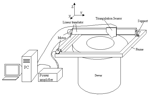 Concept for a device for flatness measurements of CCDs, using a triangulation sensor. The triangulation sensor is attached to a linear translator (Y-axis) which itself is attached to a second linear translator providing the movement in X-direction. The assembly is supported by a rectangular frame. |
The support structure for the linear translators is a rectangular frame allowing a flexible handling of the measuring device. For large mosaics you can mount the whole machine upon the dewar and use the dewar flange as the support structure. For small mosaics and single CCDs,it is more convienent to have the device mounted on a table and place the dewar underneath the instrument, as shown here.
Stepper motors in an open loop drive the two linear axes. The stepper motors and the triangulation sensor are controlled by a LabView program running on a PC,which also acquires the measurements of the triangulation sensor. The X, Y and Z coordinates are written to a text file to be analyzed afterwards.