
MAD
Introduction
The Multi-Conjugate Adaptive Optics Demonstrator (MAD) is a prototype MCAO system which aims to demonstrate in the laboratory and on sky the feasibility of different MCAO reconstruction techniques in the framework of the E-ELT concept and the 2nd Generation VLT Instruments. Afteran extended period of laboratory testing MAD was installed at the VLT Nasmyth focus for performing some validation runs.
The MAD project is led and developed by ESO with the collaboration of INAF-OsservatorioAstrofisico di Arcetri (INAF-OAA), the INAF-Osservatorio Astronomicodi Padova (INAF-OAPD) and the Faculdade de Ciências de Universidade de Lisboa (FCUL).
General Concept
MAD is designed to perform wide Field of View (FoV) adaptive optics correction in K band (2.2 µm) over 2 arcminon the sky by using relatively bright (mv < 14) Natural Guide Stars (NGS).
The MCAO correction is implemented by using two Deformable Mirrors (DM), one optically conjugated at the telescopepupil (ground layer turbulence correction) andthe second one conjugated at 8.5 km above the telescope aperture for the correction of the field anisoplanatism.
Two different wavefront sensors (WFS) are permanently installed on the MAD bench for investigating two different reconstruction techniques:
- Multi Shack-Hartmann WFS for the Star Oriented MCAO reconstruction;
- Layer Oriented Multi-Pyramid WFS for the Layer Oriented MCAO reconstruction (opto-mechanics built by INAF-OAA).
Both WFSs are able to sense simultaneously several NGS at visible wavelength but only one WFS will be used at a time. The Real-Time Computer architecture supports both the wavefront sensing modes as well as the Observing and Instrument Control Software (OS/ICS developed by INAF-OAPD).
MAD is provided with a 1 arcmin FoV IR camera (CAmera for MCAO, CAMCAO built by FCUL) scanning the MAD 2 arcmin FoV to evaluate the correction performance in K band. For testingand tuning the MAD system in the laboratory an atmospheric turbulence simulator (Multi-Atmospheric Phase screens and Stars, MAPS) is installed at the system entrance for miming a layered time-evolving atmosphere with Paranal characteristics.
MAD is built using existing technology and re-using as much as possible hardware and software key components developed in the scope of existing ESO AO systems.
System Overview
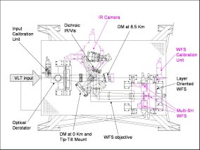
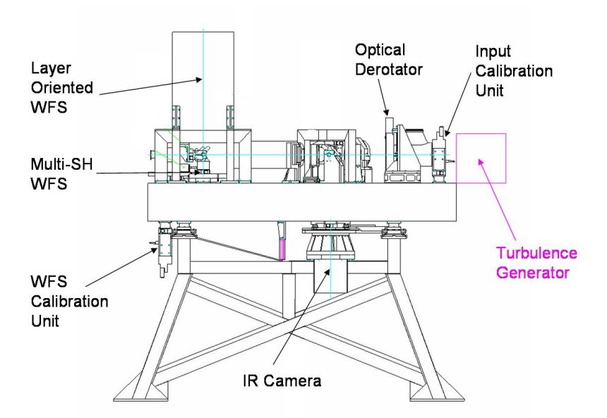
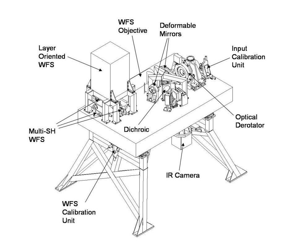
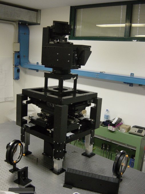
The bench is supported by a structure with four legs. The dimension of the supporting structure allows the opticalaxis to fly at 2000 mm above the floor (230 mm above the bench plane) as specified for the instruments installed the VLT Nasmyth platform.
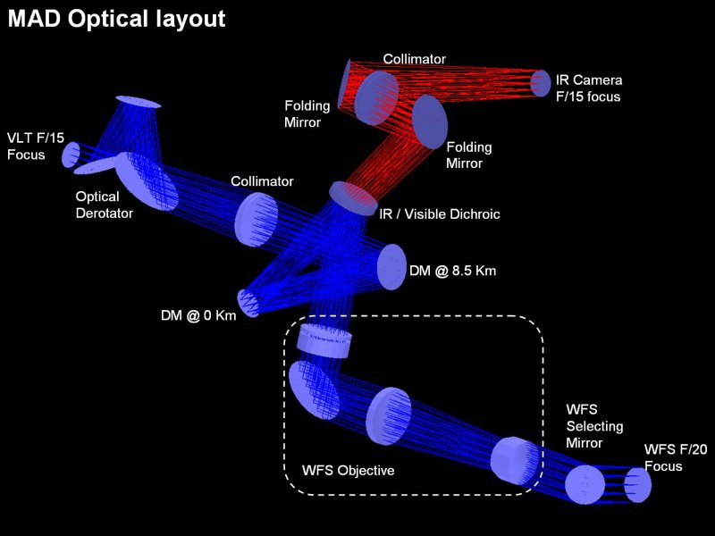
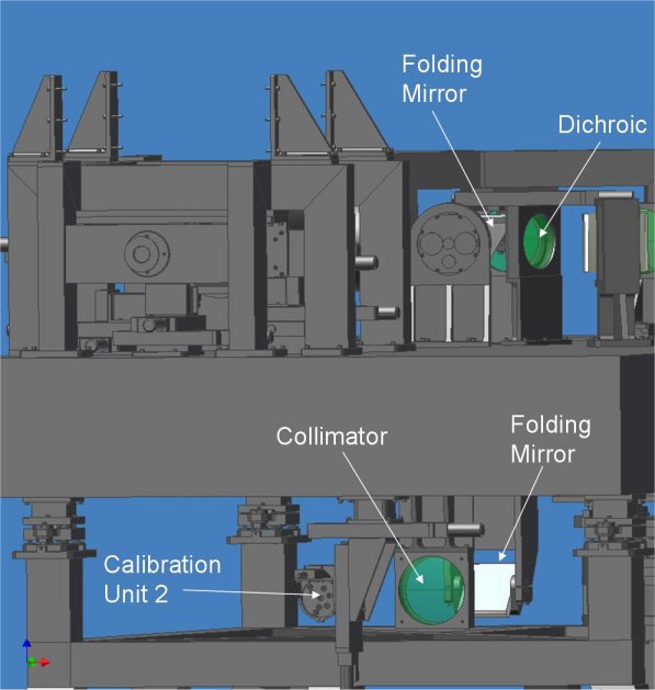
The F/15 optical beam coming from the telescope enters the MAD bench from the side. At the position of the focal plane an input calibration unit is placed to calibratethe instrument for closed loop operations. After the calibration unit an optical derotator provides to compensate the FoV rotation during the telescope tracking.
The optical beam is then collimated and folded by two DMs conjugated at 8.5 km above the telescope aperture and at the telescope pupil. A dichroic provides to reflect the visible light toward the area where the two wavefront sensors are located and transmits the IR light toward the IR camera.
A dedicated objective forms a F/20 FoV where the two wavefront sensors are located.The Multi Shack-Hartmann WFS consists of three movable SH WFS each one capable to look at any star present in the FoV. The Layer Oriented Multi Pyramid WFS is capable to sense simultaneously up to 8 NGS and image the turbulence at the two altitude where the DMs are conjugated to.
The IR path is folded downward perpendicularly to the bench plane to feed the IR camera which is able to scan the full FoV.
A turbulence generator is installed at the optical input of the MAD bench during the laboratory testing (not when MADis installed at the telescope) for simulating the Paranal turbulence conditions.
The MAD layout is shown in the pictures below.
 |
 |
 |
| MAD bench top view | MAD bench side view | MAD bench 3D view |
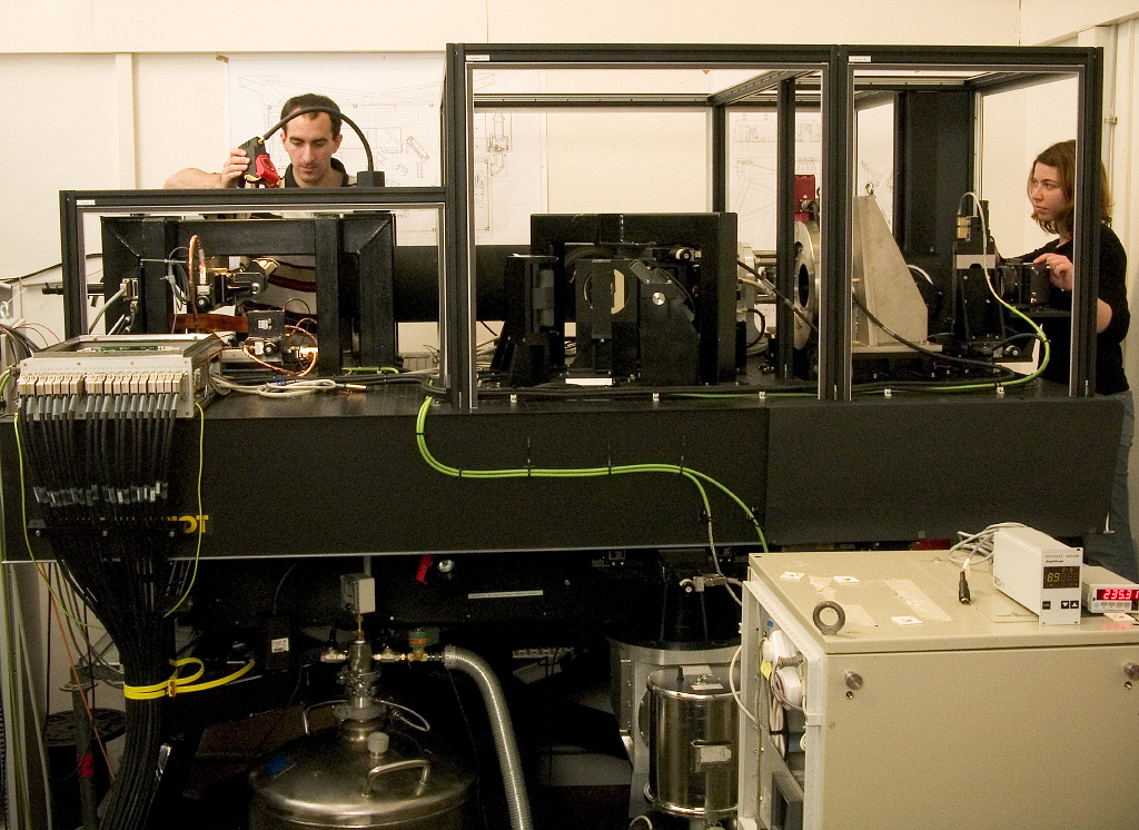 |
| MAD bench in the optical lab |
Sub-Systems Overview
- Optical Layout
- Calibration Units
- Wavefront Sensors
- Detector System
- Corrective Optics
- Real-Time Control
- IC Electronics
- Software
- Simulated Performance
- CAMCAO
- MAPS
Optical Layout
The MAD input beam is F/15 (VLT Nasmyth focus). A Field of View(FoV) of 2 arcmin is transferred through the MAD optics both for the WFS path and for the IR camera path. The FoV is de-rotated by an optical derotator and collimated by a doublet lens to re-image a telescope pupil of 60 mm in diameter. A 100 mm diameter DM is conjugated at an altitude of 8.5 km (DM-2) and a 60 mm DM is conjugated to the re-imaged telescope pupil (DM-1). A Tip-Tilt Mount(TTM) is supporting the DM-1 for the tip-tilt correction.
A dichroic splits the IR light (1.0–2.5 µm) toward the IR cameras and the visible light (0.45-0.95 µm) towardthe WFS path. A lens objective provides a flat, telecentric F/20 input beam at the both WFSs area and they are fed by two sliding 45 degree mirrors.
MAD will use two IR cameras for correction performance evaluation (replaceable, used one per time):
- The CAMCAO camera which consists of a 2k x 2k IR detector fed by a cooled reflective optical train. The CAMCAO FoV is about 1 arcmin.
- An Infrared Test Camera (ITC) which consists of a 1k x 1k IR detector fed by a cooled reflective optical train.The ITC FoV is about 17 arcsec.
Both cameras are working at the same F/15 input beam (not at the same time). To provide the corresponding F/ratioa second collimator copy of previous one is put in the collimated beam after the dichroic. A scanning unit to patrol the 2arcmin FoV with the both cameras is also provided.
The turbulence generator MAPS is located in proximity of the input F/15 to inject the turbulence inside the optical train.
 |
 |
 |
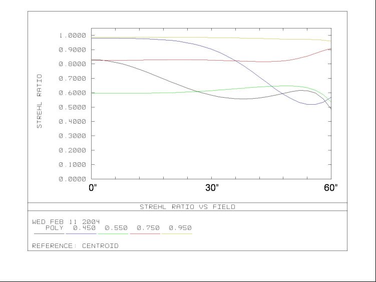
| Optical Layout< | Strehl Ratio @ F/20 focus |
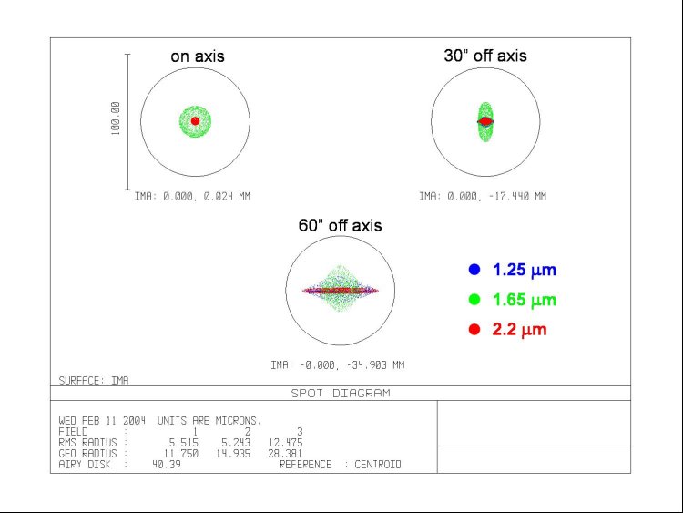
Spot Diagram @ IR focus |
Calibration Units
The MAD calibration system consists of two calibration units:
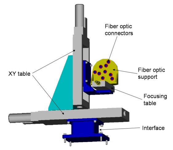
- Calibration Unit 1 @ the F/15 input focus. This Calibration Unit consists of 9 visible-IRlight illuminated fibers supported by a plate. The plate can be moved to scan the whole 2 arcmin FoV to emulate different NGS positions. A third motion along the optical axis will compensate for VLT field curvature. The calibration unitis moved out from the FoV during MAD close loop operations.
- Calibration Unit 2 @ the WFS path. This calibration unit has the same motions and fibers of the previous one and it is located below the table. A collimator identical to those installed above the bench provides to collimate the beamto be injected into the WFS objective after the deformable mirrors and before the dichroic. A sliding mirror can be insertedin the optical train to feed the WFS objective with this calibration unit.
The fibers are illuminated by an halogen lamp providing a broad band spectrum illumination from 0.45 to 2.5 µm. The Calibration Units support by default 8 single mode fibers (7 µm core), for the LOWFS calibrations, and one multimode fiber (350 µm core) for the Multi SHWFS calibrations. Additional multi mode fibers can be switched with the single mode ones for test purposes. The uniformity of the illumination of the fibers is guaranteed by using an integrating sphere located below the table and feeding both the calibration units. The illumination can be varied by moving a shield located internally to the integrating sphere between the lamp and the fiber heads.
 |
 |
| Calibration Unit 3D view | Calibration Unit 2 |
Wavefront Sensors
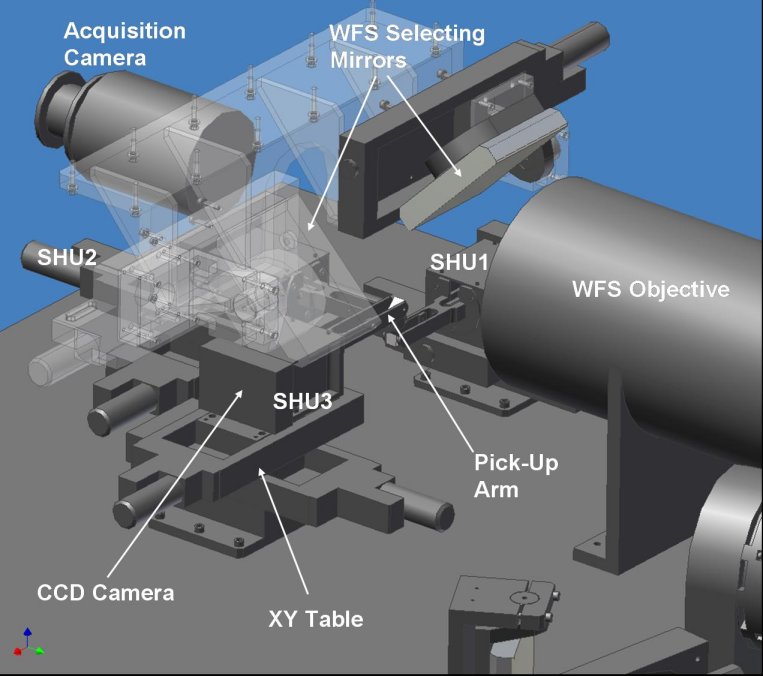
Multi Shack-Hartmann WFS (SHWFS)
The Multi Shack-Hartmann WFS consists of 3 Shack-Hartmann units (SHU) capable to scan the whole 2 arcmin FoV to pick-up the NGSs for the wavefront sensing. Each SHU is provided with an arm supporting a pick up mirror folding the light through the SHU optics, a FoV diaphragm of 2.4 arcsec located at the F/20 focus and doublet lens that re-images the telescope pupil on the lensletarray. The lenslet array is an 8 x 8 sub-apertures, 192 µm pitch, 3.2 mm focal length. A relay lens system transfers thefocal plane of the lenslet array through the WFS CCD head on the WFS CCD detector. Each subaperture is imaged over 8 x 8 pixels, 24 µm size
Each SHU is mountedon a XY motion scanning the 2 arcmin FoV and the three arms are slightly displaced in altitude with respectto the bench plane in order to avoid mutual collisions.
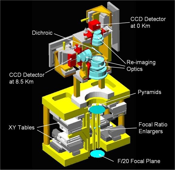
Layer Oriented Multi-Pyramid WFS (LOWFS)
The LOWFS is based on a multi pyramid WFS with eight pyramids to observe simultaneously eight NGSs. Each pyramid is supported by a small cylinder containing some re-imaging optics to enlarge the system focal ratio by a factor ~10 on the top of each pyramid. The light modulated by the pyramid is than re-imaged through two groups of lenses and the pupil image of the observed NGS is created on the plane where the WFS CCD detectors are located.
Between the two group of lenses a dichroic splits the light toward two WFS cameras slightly displaced along the optical axis in order to provide the footprint geometries proper of the conjugation altitudes of the two DMs of MAD.
 |
 |
 |
 |
| Multi SH WFS 3D view | SH Lenslet Array | LOWFS 3D view | LOWFS at OAA |
Detector System
CCD Detectors
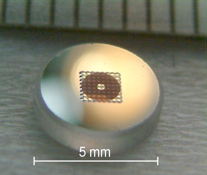
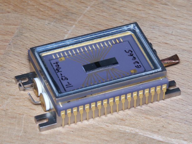
The MAD detector system consists of 5 WFS CCD cameras (3 for the SHWFS and 2 for the LOWFS) based on the Marconi E2V CCD39 chip. The CCD39 format is 80 x 80 pixel, 24 µm size, and four outputs.
The CCD39 chips are provided by E2V inside a Peltier cooler capable to reach 40 degree Celsius below the external ambient temperature. The Peltier package is allocated inside a small compact CCD head box. A flat flexible PCB board is extended up to thepre-amplifier boards and allow the WFS cameras to be moved without any friction due to rigid cables.
CCD Control Electronics
The CCD39 are controlled by a FIERA system. For the SHWFS 12outputs will be used simultaneously, for the LOWFS only 8 outputs. For the SHWFS, FIERA will be able to drive the detectors simultaneously at the same frame rate while for the LOWFS it is required to run the two detectors at different frame rates. The maximum frame rate required is 400 Hz. Theread-out modes are taken from those developed for NAOS. FIERA will not drive the two WFS at the same time.
Sub-aperture Layout
In the SHWFS the useful surface of the detectors is divided in 8 x 8 sub-apertures, 8 x 8 pixels each. The number of useful sub-apertures is 52 each having 2.4 arcsec FoV.
In the LOWFS the detector conjugated with the ground layer has a fixed binning of 2 x 2 while the detector conjugated at 8.5 km has a fixed binning of 4 x 4. Taking into account the difference of the footprint size of the 2 arcmin FoV at the two altitudes the resulting sub-aperture grid is 8 x 8 for the ground conjugated detector and 7 x 7 for the high altitude conjugated one.
Acquisition Camera
The aim of the acquisition camera is to provide the WFSs with a precise measurement of the NGSs location for accurate positioningof both the SHU and the pyramids. The Acquisition Camera is a New Technical CCD based on the E2V CCD47-20 (1024 x 1024 pixel, 13 µm size), coupled to a lens objective for the acquisition of the whole 2 arcmin FoV. The resulting scale on the detector is ~0.20 arcsec/pixel optimal for accurate NGS centroid measurements.
 |
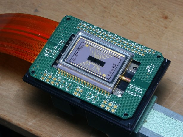 |
| CCD39 included in the Peltier | PCB board |
Corrective Optics
The MAD wavefront correction is performed by two bimorph Deformable Mirrors and a Tip-Tilt Mount. The two DMs have been developed in the framework of two existing AO projects. The ground conjugated DM is a copy of the SINFONI one witha pupil diameter of 60 mm. The DM conjugated at 8.5 km is a copy of the MACAO-VLTIDM with a pupil diameter of 100 mm. The Tip-Tilt Mount supporting the 60 mm pupil DM is a copy of the SINFONI
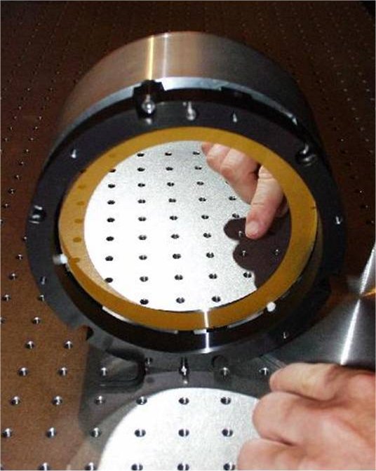
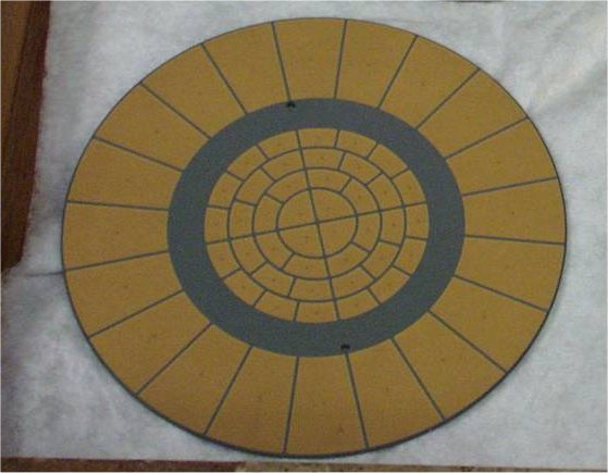
Deformable Mirrors
Both the bimorph DMs have 60 electrodes with almost the same geometry and they have been developed by CILAS (France). The 60 electrodes are gold printed and sandwiched between two 0.8mm thick PZT layers with opposite polarization. The outside surfaceof the PZT layers are grounded and covered with a 0.1mm glass layer, aluminum coated. Applying a voltage to one electrode produces a constant curvature over its surface of ~5km for 1V.
The 4 central rings (40 electrodes) are included in the pupil (or in the footprint at 8.5 km) while the 20 remaining electrodesare deposited outside the pupil and are used to constrain the edge of the pupil (correction of curvature free aberrations: tip/tilt, astigmatism…). The DM provides the 3s stroke to compensate all atmospheric aberrations up to a seeing of 1arcsec (measured at 500nm).
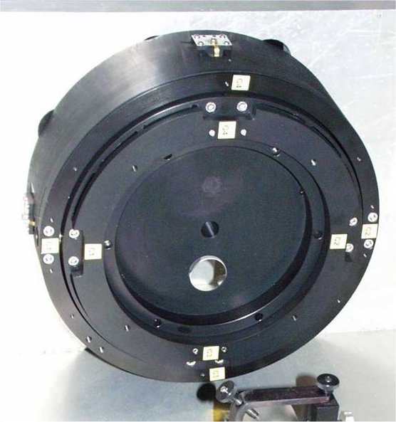
Titp-Tilt Mount (TTM)
To provide additional stroke, the 60 mm pupil DM is mounted to the Tip-Tilt Mount designed and built by Observatoire de Paris Meudon, which provides ±240arcsec a mechanical stroke, i.e. ±3.6 arcsec on the sky, with a 100Hz -3dB closed loopbandwidth.
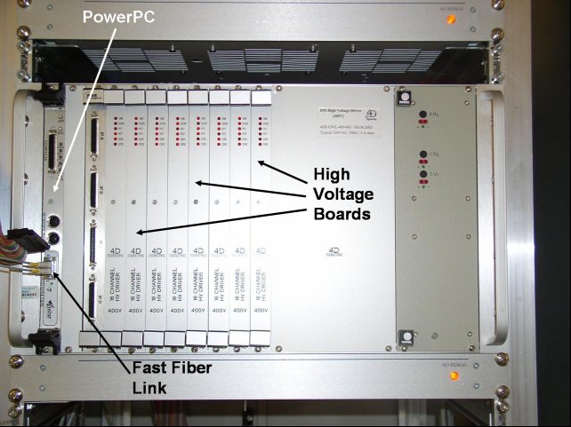
DM Control Electronics
The DM controller is a VME-bus system, based on ESO SW and HW standards to a large extent. The central element is a Motorola PowerPC board, running embedded VxWorks. The DM controller, essentially a fast 2x60-channel programmable high voltage generator, is providing a drive voltage of +/-400 volts for the nominal stroke of the DM electrodes and it controls both DMs. The correctionvector is sent by the Real-Time computer to the DM controller through a dedicated fast fiber link. The DM controller has been specified by ESO, and built according to specification by 4D Engineering (Germany).
 |
 |
 |
 |
| DM 60 mm | Electrodes Geometry | Tip-Tilt Mount | The DM controller |
Real-Time Control
The MAD Real-Time Control has been designed to support both the Star Oriented and the Layer Oriented wavefront sensing techniques and to implement both the Global and the Local Reconstruction. Even if the Global Reconstruction is proper of the Star Oriented mode and the Local Reconstruction is proper of the Layer Oriented mode these WFS techniques can be mutually exchanged with respect to the reconstruction approaches by combining numerically (Star Oriented) or optically (Layer Oriented)the light of the sensed NGSs. Regardless the WFS and Reconstruction approaches used, the Real-Time Control performs the following operations both in open and closed loop:
- acquisition of the data from the wavefront sensor detectors;
- computation of the Interaction and Reconstruction matrices;
- computation of the correction vector through the Reconstruction Matrix;
- sending the flat, reference or correction commands to the DMs
- basic manipulation of the acquired/produced data;
- real-time display of the acquired/produced data;
- producing diagnostics for checking the quality of the observation;
- offloading the tip-tilt signal to the TTM or the telescope optics.
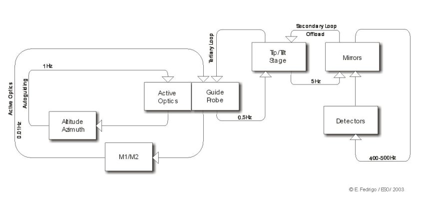
The MAD Real-Time Computer Subsystem is organized in three nested control loops. The primary loop which is the main loop, where the disturbed wavefront is compensated. It goes from the wavefront sensors to the deformablemirrors and it runs between 400 and 500 Hz. The secondary loop where a portion of the tip-tilt component compensated by the DMs is off-loaded at each cycle to the TTM (5 Hz). The tertiary loop where the TTM is out of stroke for slow large movements: the control loop computes this slow drift and it makes it available to the MAD OS to compensate for it (0.2 Hz).
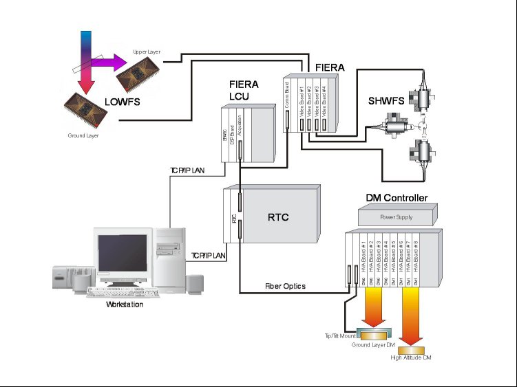
The MAD Real-Time Control Hardware architecture is shown in the picture below. A standard ESO instrument workstation (WS) is used to interface to the Local Control Unit (LCU) and hosting the WS components of the MAD Real-Time Control SW. It will run other WS components of the MAD system. The supervisory Computer (LCU) is a PowerPC (PPC) 604 mountable in a VME rack. It has a RS232 serial link going to the High Voltage Amplifier for housekeeping operations. The Real-Time Computer is theDy4 CHAMP-AV board, a Quad-G4 board that mounts 4 PowerPC 7410 running at 500 MHz. The connection between theReal-Time Computerand FIERA is assured by a 32 bit digital I/O board
 |
 |
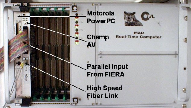 |
| Real-Time Computer Subsystem loops | R-T Control HW architecture< | MAD Real Time Computer |
Instrument Control Electronics
Additional control electronics are implemented in MAD besides the FIERA, the DM and TTM controllers and the Real-Time Computer. MAD has 38 motion axes which control is supervised by two LCUs (one for the MAD bench and the SHWFS in total 18 axes, one for the LOWFS in total 20 axes). The Acquisition Camera has its dedicated technical CCD controller and theIR camera is driven by an IRACEcontroller. In total MAD has 6 LCUs, which supervise 38 motion axes, 7 detectors and 3 active components having 122 channels(2 x 60 DM electrodes and tip-tilt axes).
Software
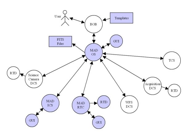
The diagram below provides an overview of the software architecture of MAD, showing the software systems which are operational during a MAD observation. MAD comprises a number of separatesubsystems under software control, these subsystems are:
 |
| Software Architecture |
- Science Camera
The IR cameras are read out by an IRACE controller. The standard IRACE DCS SW and RTD are used with no additional development. The science camera has the capability to scan the FoV. - WFS CCD Detector
Either two CCDs for the Layer Oriented wavefront sensor or three CCDs for the Shack-Hartmann wavefront sensor read out by a FIERA CCD controller. Only one of the wavefront sensors at a time can be connected to FIERA. The standard FIERA DCS SWand RTD are used. - Acquisition Camera
The standard TCCD DCS SW and RTD are used. - Real-Time Computer
The real-time computer acquires wavefront sensor data from the FIERA controller, applies the AO control algorithm, drives the corrective optics and provides display facilities for imaging the WFS data. - Instrument Control
Driving the motorised functions and calibration units, based on the VLT standard ICS “icb”. - Observing Software
The software which coordinates the activities of the other MAD subsystems. Based on the VLT standard OS “BOSS”. The OS in turn is driven by MAD specific templates which are scheduled by the Broker of Observation Blocks (BOB).
The Telescope Control Software (TCS) provides the interface by which MAD derotate the filed with the optical derotator and off-load high stroke Tip/Tilt and Focus errors to the telescope. The ESO standard RTD application is used to display the data from the Infrared Science camera, the acquisition camera and the WFS data from the RTC.
As a technology demonstrator the MAD software will not provide the same level of automation or user support that would be provided in a standard VLT instrument, rather emphasis is placed upon providing all of the low level functionality requiredto demonstrate the correct operation of the wavefront sensing techniques and AO control strategies.
Simulated Performance
The MAD correction performance is evaluated in K (2.2 µm) band. Extensive numerical simulations have been implemented for simulatingthe MAD system both in the Star Oriented mode with the Multi SHWFS and in the Layer Oriented mode with the LOWFS.
Star Oriented Mode
In the case of Star Oriented and Global Reconstruction the three SHWFS have been considered looking at two asterisms of three mv=12 NGS each equally distributed on a circle of diameter 1 and 2 arcmin. The Strehl maps over the specified FoV have been computed and hereafter only the values of the maximum, minimum and on-axis (FoV centre) Strehl have been summarized. Three cases of seeing have been considered:0.4, 0.73 and 1.0 arcsec. The values reported here include the MADwavefront error budget.
| 1 arcmin diameter FoV |
On-axis Strehl | Max Strehl | Min Strehl |
| Seeing 0.73 arcsec | 0.26 | 0.31 | 0.10 |
| Seeing 0.40 arcsec | 0.53 | 0.58 | 0.34 |
| Seeing 1.00 arcsec | 0.11 | 0.16 | 0.04 |
| 2 arcmin diameter FoV | On-axis Strehl | Max Strehl | Min Strehl |
| Seeing 0.73 arcsec | 0.10 | 0.24 | 0.07 |
| Seeing 0.40 arcsec | 0.32 | 0.48 | 0.24 |
| Seeing 1.00 arcsec | 0.04 | 0.11 | 0.03 |
Layer Oriented Mode
For the Layer Oriented and Local Reconstruction only the cases of 0.73 arcsec seeing has been considered. Different asterisms have beenused varying the number or stars used for the wavefront sensing. The same cases of Star Oriented (three mv=12 stars on a circle of 1 and 2 arcmin diameter) have been simulated and, additionally, real asterisms with 6 and 8 stars have been used. The magnitudes of the single stars have been scaled uniformly in order to achieve different total integrated magnitude for the related asterism. Also in this case the Strehl maps have been computed. Hereafter only the values of the maximum, minimum and on-axis (FoV centre) Strehl have been summarized. The values reported here include the MAD wavefront error budget.
| #stars/mv/FoV | On-axis Strehl | Max Strehl | Min Strehl |
| 3 / 10.8 / 1' | 0.36 | 0.39 | 0.26 |
| 3 / 10.8 / 2' | 0.14 | 0.28 | 0.08 |
| 6 / 10.0 / 2' | 0.30 | 0.39 | 0.12 |
| 6 / 12.0 / 2' | 0.28 | 0.36 | 0.11 |
| 6 / 14.0 / 2' | 0.20 | 0.26 | 0.08 |
| 8 / 10.0 / 2' | 0.30 | 0.39 | 0.12 |
| 8 / 12.0 / 2' | 0.27 | 0.37 | 0.09 |
| 8 / 14.0 / 2' | 0.17 | 0.25 | 0.04< |
CAMCAO
The CAMCAO IR camera is a 1 arcmin FoV camera with pixel scale of 0.028 arcsec/pixel (Nyquist sampling in K Band) built by FCUL. CAMCAO is used to evaluate the wide FoV MCAO correction of MAD. CAMCAO is based on a 2k x 2k Hawaii2 IR detector controlledby a standard IRACE system. The camera will have standard IR band filters (J, H, K', Br-Gamma and Br-Gamma continuum) mounted on a manually positionable filter wheel. CAMCAO is placed in the F/15 focussed beam after the dichroic and it is provided with an optical system cooled by a liquid Nitrogen bath cryostat. Field and pupil cold stops are implemented to significantly reduce the background and the stray-light.The CAMCAO IR camera optics provide diffraction limited images down to J Band.
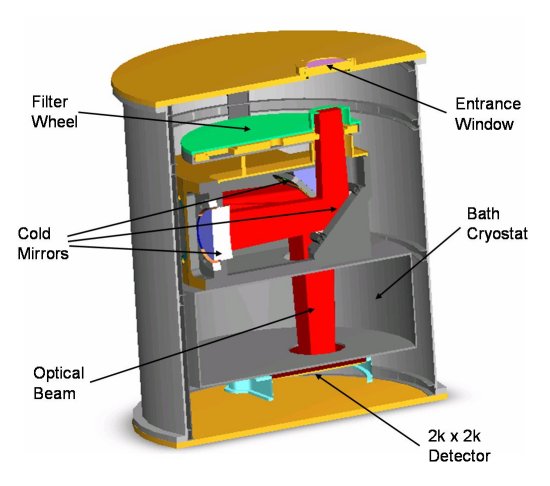 |
| CAMCAO 3D view |
MAPS
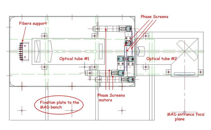
The MAPS goal is to emulate a time evolving three-dimensional atmosphere whose induced aberrations are injected into MAD. The characteristics of the atmospheric turbulenceshall be similar to those of the Paranal observatory during median seeing conditions. The evolving atmosphere is reproduced by some rotating transmissive plates, called Phase Screens (PS). The refractive index in the PS substrate is modified locally in order to produce a phase shift in an electromagnetic wave passing through it.
The Natural Guide Stars (NGS) are emulated by visible-IR light transmissive fibres. The fiber positions will be changeable to create the desired star configuration in a FoV of 2 arcmin. A first group of lenses collimates the light beams from the NGSs and allows the telescope pupil to be created. Different PSs are located in the collimated beams to emulate the atmospheric layers at different altitude. One phase screen is located close to the telescope pupil to emulate the ground layer. The PSs have different turbulence power according to the expected vertical distribution.
The evolving atmosphere is emulated by rotating the PSs at different speeds according to the wind speed vertical profile. The PS separations and positions can be varied in order to modify the atmospheric anisoplanatism and the speeds can be adjusted to reproduce a wide range of atmospheric correlation times.
Moreover the PS are interchangeable in order to emulate a selected range of seeing conditions. A second group of lenses re-images the artificial NGSs whose wavefront quality is degraded by the PSs. The distorted wavefrontsare then injected into MAD for MCAO correction. MAPS is used only for laboratory testing.
In the table below are shown some animated examples of the wavefront and PSF generated with MAPS.
 |
  |
  |
| MAPS 2D view | Movies | |
What's new?
Check for the next lunch Talk.
Quick Links
- Home
- Adaptive Optics group expertise and activities
- Adaptive Optics Systems
- Adaptive Optics Technologies
- AO lunch talks
- Other useful links
Special Event: 20 years of Adaptive Optics at ESO
Contact Us