EFOSC2 Polarimetric Optical Elements
Note that since EFOSC2 was moved to the Nasmyth focus of the NTT there is a significant instrumental polarisation that varies with telescope pointing. We are working to characterise this effect, but users should be aware that it may limit the accuracy to which polarisation can be measured. When preparing proposals for polarisation, extra time for observation of a large number of calibration stars should be included.
Content
- Half Wave Plate
- Quarter Wave Plate
- Wollaston Prisms
- Wollaston Mask/Slit
- Polarimetric imaging configuration
- Spectropolarimetry configuration
- Identifying the acquisition reference pixel
Half Wave Plate
A super-achromatic Half Wave Plate (HWP) is available for use in EFOSC2. The HWP can be moved in and out of the optical path as desired, can be set to continuous rotation to fully depolarise the incoming radiation, and can also be set to a particular angle (typically one chooses 0, 22.5, 45 and 67.5 degree positions). With this device one can obtain a full linear polarisation measurement without rotating the adaptor.
The HWP takes 2.3 seconds to make a complete rotation (rotates clockwise as seen from the CCD). We recommend at least 10 seconds of complete rotation to ensure that the incoming radiation is fully depolarised (flat fields, for example).
HWP reset problem - Very important!
If the HWP is set into continuous rotation and the exposure is long it goes through many full rotation. At the end of the observation, in order to reset to zero, it tries to undo all the rotations instead of trying to merely undo modulo 360 degrees - This is a bug for which we have a "fix" which has been incorporated into all the observing templates which call for continuous rotation of the HWP. We simply re-initialise the HWP at the end of the template.
A problem will arise, however, if such a template were to be aborted midway through the execution. The HWP will continue to rotate and any subsequent command to derotate the HWP will result in a timeout error; and unless the HWP is reset to zero no other template can be executed The only solution in such cases is to stop the HWP rotation from the OS panel and cold-start EFOSC2 on the IS panel (the telescope operator will do this job; the astronomer's duty only consists of reminding the operator of the problem, if necessary).
Quarter Wave Plate
In EFOSC2, besides the half-wave plate for polarimetry, there is also a quarter-wave plate. Onnly one plate can be mounted at once, as they occupy the same space within EFOSC2. The HWP is used for measuring linear polarisation, while the QWP measures circular polarisation. The use of the QWP is the same as the HWP in terms of instrumentation, although there are separate (and nearly identical) templates for p2pp with QW in their names.
Wollaston Prisms
A Wollaston prism splits the (unpolarised) image of an object into 2 images of orthogonal polarisations. The 2 images symmetrically straddle the location where the unpolarised image would have been in the absence of the prism. There are 2 Wollaston prisms available for use with EFOSC2
- 20" Wollaston prism: the image separation is 20 arcseconds - imaging and spectropolarimetry
- 10" Wollaston prism: the image separation is 10 arcseconds - only imaging
The Wollaston prisms can be used for both polarimetric imaging and spectropolarimetry. In the imaging mode they are mounted on the grism wheel while they go on the filter wheel for spectropolarimetry. However note that the 10" Wollaston prism does not fit on the filter wheel and so cannot be used for spectropolarimetry.
The orientation of the image separation can be changed by rotating the prisms in the wheels. At EFOSC2 the prisms are aligned so as to split the images either along the x- or the y-axis of the CCD.
Since the dispersion axis of EFOSC2 is always along the y-axis of the CCD the two spectra must be split along the x-axis for spectropolarimetry.
Wollaston Masks
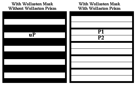
Since a Wollaston prism forms 2 images of each object on the CCD one has to mask the field of view such that second image of a section of the field does not coincide with the first image of any other section of the field. One achieves this by masking alternate strips of the field of view - the width of the masked and the transparent sections being equal to the separation between the images produced by the Wollaston prism.
Corresponding to the two possible directions along which the prisms can split the image there are two types of Wollaston masks - parallel masks in which the strips are parallel to the x-axis and perpendicular masks in which the masks are perpendicular to the x-axis. Note the prisms must be oriented so as to split the images perpendicular to the long axis of the masking strips.
For spectropolarimetry since the spectra are split along the slit the masking strips run perpendicular to the slit.
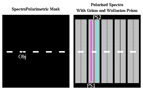
A spectropolarimetric mask is essentially a long slit which has been masked at regular intervals.
One can, if needed, make other wollaston masks, using the MOS punching tool (for example, if 2 targets are so located that only one of them can be imaged at a time with the current set of masks).
Note : Because of the masking only half the field can be imaged at any time.
Polarimetric Imaging Configuration

The panel on the left shows the wollaston mask for imaging. It consists of a plate from which a series of parallel strips are cut leaving alternate opaque (black) and transparent (white) strips. Only objects falling on a white strip are imaged on the CCD. When the Wollaston prism is introduced in the light path (after the mask) the white unpolarised areas are split into two strips of orthogonal polarisation. These polarised strips are positioned symmetrically on either side of the original strip. Thus an object located at uP originally (i.e. the unpolarised image) would split into 2 images P1 and P2 of orthogonal polarisations.
There are both parallel (shown above) and perpendicular masks (rotated by 90 degrees). The Wollaston prism must be rotated in its holder such that the throw of the image is aligned perpendicular to the strips. Further there are 2 Wollaston prisms which provide image separations of 10" and 20" and corresponding masks as well. A summary of the available masks is given below. Note that the opaque strips are slightly smaller than the transparent sections - this neatly identifies the complementary pair even in a crowded field.
Length |
Width |
||
|---|---|---|---|
SpectroPolarimetric Configuration

Analogous to the imaging mask there is a spectropolarimetric slit which is essentially an ordinary long slit masked at regular intervals (left panel). Thus an objected located at Obj will yield 2 spectra PS1 and PS2 of orthogonal polarisations when a grism and Wollaston prism is introduced. The location of the spectropolarimetric slit has been marked on the right hand panel for reference.
For obvious reasons only a perpendicular mask is available for spectropolarimetry.
There are 2 spectropolarimetric masks :
- 1" slit with 3 transparent sections of a little less than 20" width each and separated by a little more than 20"
- 1.5" slit with 8 transparent sections of a little less than 20" width each and separated by a little more than 20"
Identifying the Acquisition Reference Pixel
(First read the above two sections)
One needs to identify a good object location on the Wollaston masks ( uP in imaging and Obj in spectropolarimetry) such that (i) it is located on the transparent section and (ii) its two polarised images/spectra will fall on good pixels.
It is this location (pixel value) taken from the unpolarised mask image which has to be used in the acquisition template. This is because the acquisition image (for science images) is taken without the wollaston prism and mask. In order to identify/select a good target location follow the procedure given below :
- Take an image of the flat-field screen with the Grism position free but with the Wollaston mask in the path. You should get an alternating series of bright and dark strips as shown above.
- Locate a good spot on one of the bright strips ( uP in imaging and Obj in spectropolarimetry) avoiding the vicinity of bad pixels and note the pixel co-ordinates. It is important that there are no bad pixels for 10-20" on either side of this selected location. These co-ordinates must be used in the EFOSC_img_acq_Polarimetry acquisition template for imaging and EFOSC_img_acq_MoveToSlit for spectropolarimetry
- This mask image is most easily obtained by the support astronomer directly using the controls on the OS panel (not through BOB). The observer should have a look at the mask image (during the afternoon or the previous day) and select the location for his targets.
