
MAVIS - MCAO-Assisted Visible Imager and Spectrograph
Content
• Baseline Specification
• Schedule
• Instrument description
• Science with MAVIS
• Adaptive Optics and Multi-Conjugate Adaptive Optics
MAVIS is intended to be installed at the Nasmyth A focus of the VLT UT4 (replacing Hawk-I/GRAAL) with the AOF and is made of two main parts: an Adaptive Optics (AO) system that cancels the image blurring induced by atmospheric turbulence and its post focal instrumentation, an imager and an IFU spectrograph, both covering the visible part of the light spectrum.

| Principle Investigator |
Francois Rigaut |
| Consortium | |
| Project manager |
Andreas Förster |
| Project scientist |
Harald Kuntschner |
| Project system engineer |
Ulf Seemann |
| Instrument approval | December 2020 |
| Project status |
Final Design Review (Phase B) |
| Location | Nasmyth A of UT4 |
General Properties + AO Module |
Imager |
||
| Focus | Nasmyth A VLT-AOF (UT4) |
Field of View | 30"x30" |
| NGS Field of View | 120" diameter disk | Pixel Scale | 7.36mas/pix |
| Number of NGS | Up to 3 | Sensitivity | V>29mag(5σ) in 1hr |
| Limiting magnitude | Hmag⩾18.5 | Filters | u'g'r'i'z', various narrow bands |
| LGS beacons | Up to 8 on a circle of 17.5" ⌀ |
Spectrograph |
|
| Sky coverage | ⩾50% at the South Galactic Pole | IFU Spaxel and FoV, fine | 20-25mas spaxels, 2.5"x3.6" FoV |
| Ensquared energy | >15% within 50mas at 550nm | IFU Spaxel and FoV, coarse | 40-50mas spaxels, 5"x7.2" FoV |
| Strehl | >8% (12% goal) in V-band | LR-Blue Spectral Config. | R=5,900 λ/Δλ, 370-720nm |
| LR-Red Spectral Config. | R=5,900 λ/Δλ, 510-935nm | ||
| HR-Blue Spectral Config. | R=14,700 λ/Δλ, 425-550nm | ||
| HR-Red Spectral Config. | R=11,500 λ/Δλ, 630-880nm | ||
Schedule
- First light at the telescope – 2031
- Preliminary Acceptance Europe (PAE/A) – 2030
- Final Design Review (FDR) – October 2025
- Long Lead Items Review (LLI) – 2023 (Completed)
- Preliminary Design Review (PDR) – 2023 (Completed)
- ESO project approval – December, 2020 (Approveded)
- Phase A study review meeting – May 26th, 2020 (Completed)
Instrument description
MAVIS will take advantage of the superb performance of the AOF (powerful Laser Guide Stars and Deformable Secondary Mirror). MAVIS will push AO toward the visible, and, using the Multi-Conjugate AO concept, will provide a 30”x30” wide field of view at an angular resolution close to the diffraction limit of the 8-m aperture. This is unprecedented in ground-based instrumentation.
The figure on the below gives a 3D view of how MAVIS will fit on the AOF Nasmyth platform, opposite to MUSE.

Science with MAVIS
MAVIS will be a unique facility. With an angular resolution of down to 18 milliarcseconds (close to 50 times better than the seeing limited conditions encountered without Adaptive Optics) and powerful and sensitive post-focal instrumentation, MAVIS will be instrumental to bring answers to a number of astrophysical science questions regarding stellar evolution and star formation, physical composition of mid-redshift galaxies, how early galaxies assemble, or closer to us, weather monitoring on our solar system planets and moons.
The Science Case (https://arxiv.org/abs/2009.09242) has been developed during phase A. A call for white papers was widely answered by the community, resulting in over 50 white papers involving 150 researchers from across the international astronomy community.
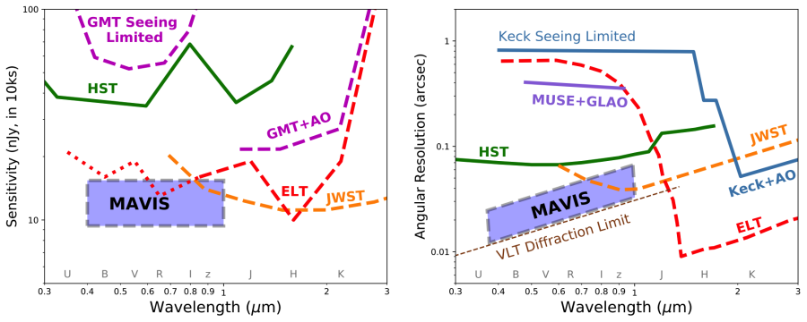
Comparison of MAVIS with existing (solid line) and future (dashed line, or dotted where performance is less certain) general-purpose observing facilities. Data were extracted from public sources (instrument handbooks, performance simulators, and exposure time calculators). Left: Limiting point-source sensitivity as a function of wavelength for a 10σ measurement with 10ksec of integration. The approximate region for MAVIS is indicated, based on the MAVIS ETC. Right: Angular resolution as a function of wavelength, with MAVIS operating at or near the VLT diffraction limit. MAVIS compares favourably with ELT-class facilities for sensitivity at optical wavelengths, and uniquely combines this with high angular resolution.
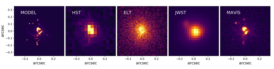
Example of a morphological study of an high-z galaxy as observed with HST, ELT-MICADO, JWST-NIRCam and MAVIS in I band. Based on the z=5 high resolution simulated “Althaea” galaxy (Pallottini et al. 2017), shown in the first panel. The other panels show instead how the same target of 25 AB magnitude would appear in I-band if observed with different facilities for a fixed exposure time (1h). In the VLT/MAVIS image, clumpy regions as faint as 29th AB mag are detected with a signal-to-noise-ratio 5.
Adaptive Optics and Multi-Conjugate Adaptive Optics
Adaptive Optics (AO) is a technique to compensate quickly varying optical aberrations in an optical system. In astronomy, telescope images from astronomical objects are blurred by atmospheric turbulence. By using AO, astronomers can cancel out these blurs and restore images close to the ultimate image quality imposed by the telescope, something called diffraction limit (and given by the ratio of the imaging wavelength and the telescope aperture diameter, λ/D). The light coming from a star through atmospheric turbulence, after being collected by the telescope, bounces off a deformable mirror (DM) that is shaped to compensate the corrugation of the light wave. A Wavefront Sensor (WFS) measures the aberrated light wave, and, through a control computer, is used to control the shape of the DM. The resulting compensated light can be captured by regular post focal instrumentation, imagers or spectrographs, with greatly improved clarity (angular resolution) with respect to the natural seeing limit imposed by atmospheric turbulence.
One of the limitation of AO is that the correction is only valid in a very small patch of sky (depending on the wavelength, from a few arcsec to a few tens of arcsec). Multi-Conjugate Adaptive Optics, or MCAO as used in MAVIS, solves this problem by using a series of DMs to compensate the turbulence in volume. To do so, MCAO uses several guide stars to measure the light wave aberrations in several directions, and using a tomographic reconstruction process, determine the best commands to apply to the DMs, as illustrated in the figure on the right/below.
The net result of MCAO is that the corrected field of view is much enlarged with respect to what can be produced with regular AO, typically by a factor of 10 to 20 in area. In addition, one can tweak the uniformity of the output image quality (IQ) to obtain the most uniform IQ, something important for the extraction of quantitative photometry and astrometry from the post-focal instrumentation data (images and spectra).
