
AMBER Warm Optics
We will briefly present the general layout of the AMBER warm optics in this section. Technical descriptions of the instrument can be found in Petrov et al. 2007 and Robbe-Dubois et al. 2007.
The main function of the warm optics is to take the multimode white light coming from the telescopes and make spatial filtering using single mode fibers, correct for the atmospheric dispersion and polarisation effects, and provide with proper calibration.
AMBER Warm Optics Layout
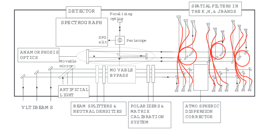
Shown to the right is a drawing (from Robbe-Dubois et al. 2007) showing the position of the various optical modules.
The function of the various optical modules are the following:
- Calibration and Alignment Unit (CAU, not shown): Provides calibration light sources for the internal calibration and alignment of the instrument.
- Neutral Density filters (NDN): Allows the attenuation of the incoming light by factors of 1, 10, or 100.
- The Bypass (BYP): A 45° mirror allowing the light to bypass the single mode fibers and thus make direct imaging.
Note: Used only for maintenance purposes. - Polarisers (POL): Polarsation filters for the incoming light. Improves the measured Visibility.
- Matrix Calibration System (MCS): A set of λ/4 plates which can be introduced in the beam sent by the CAU in order to necessary to calibrate the matrix of the "pixel to visibility" (P2V) linear relation.
- Spatial Filters (SPF):
- The three sets of spatial filter modules are K, H, and J. The bands are selected with dichroics for K and H, and a mirror for J. For each band, each of the three beams are injected in a single mode optical fiber. On the other side of the table the light from the fibre (now single mode) is recombined with the light from the other two bands using dichroics. The final product after this stage are three beams containing the K, H, and J bands now in single mode.
- Atmospheric Dispersion Corrector (ADC): The H and Jbands are strongly affected by the atmospheric dispersion and thus the ADC is installed between the K and H band spatial filters.
- Anamorphic mirrors (SPF): The anamorphic mirrors will make the beams anamorphic by a factor of 4 in the x- with respect to the y-axis and feed the beams to the SPG.
- Spectrograph (SPG): The Spectrograph is described in detail here.
- Detector (DET): The Detector is described in more detail here.
- Shutters: There are two sets of shutters in AMBER. The first set of three is used for selecting the input beams, the second set of nine (with 3 for each band) are used to select the beams in the three bands.
AMBER Warm Optics Light Path
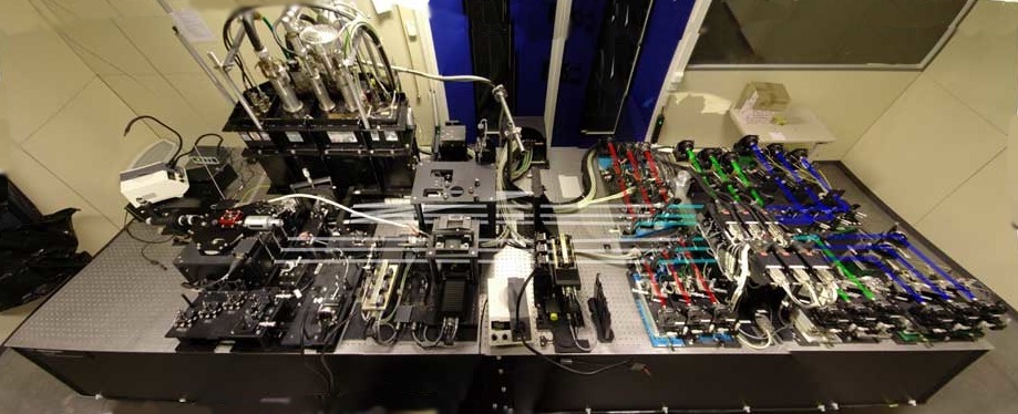
To the right the AMBER warm optics layout is shown with the three beams superimposed. White is the raw incoming light (coming either from the telescopes or the Calibration and Alignment Unit (CAU), red, the K-band, green, the H-band, and, blue, the J-band light path.
Image courtesy Florentin Millour and the AMBER consortium.