
Instrument Description
Contents
Common Principle
Fig. 1: General principle scheme of the PRIMA facility |
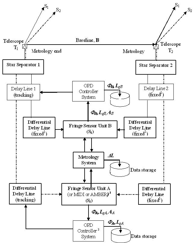
The light from the observed object and reference is collected by a pair of telescopes (either UT-8m or AT-1.8m). The selection of the reference star is made within the anisoplanatic angle at the selected wavelength.
The two field separation is performed by the Star Separator System (STS). The STS collimates the two beams and sends them to the delay lines tunnel.
The main Delay Lines compensate for both beams the optical path difference introduced by Earth rotation. They also transfer the pupil from the telescope to the selected instrument.
Before getting to the instruments, both beams are directed to the Differential Delay Lines. The DDL's function is to compensate the relative Optical Path Difference introduced between both beams coming from the same telescope.
After the DDL, the reference beams are directed to the Fringe Sensor Unit B. The FSU B generates the interference and analyses the fringe pattern in order to determine the Optical Path Difference to be compensated by the main DL and the DDL. The FSU B is used as a fringe tracker for both reference and object. The two beams coming from the scientific object are directed either to the instruments ( MIDI, or AMBER) in imaging mode or to the Fringe Sensor Unit A in case of astrometry mode.
At the level of the FSU A/B and Instrument, the metrology is introduced in the optical path. The metrology measures in real time the relative optical path difference between the reference and the object beams. The fringe patterns of both objects combined with metrology measurement are analysed to determine either the angular separation of both objects in the sky (astrometry) or the complex visibility of the science object (imaging Mode).
The PRIMA Subsystems
PRIMA is composed of four different subsystems:
The Star Separator System (STS)
The Star Separator is an opto-mechanical system for the UTs and ATs located at the Coudé foci feeding two arbitrary objects from the Coudé field of view into the Delay Lines of the VLTI. The Star Separator allows the transmission of two fields up to 1 arcmin apart in the sky and 2 (for the UTs) resp. 9 (for the ATs) arcsec in diameter towards the Delay Lines. The light is then collimated into two 80 mm diameter beams.
The system implements several degrees of freedom to allow slow pupil alignment and tilt adjustments during operation. The possibility of counter-chopping will be foreseen for operation at 10 μm. Tracking accuracy requirement is 10 mas with 2 mas resolution.
The Differential delay lines (DDL)
The difference of the white light fringe position of the primary and of the secondary star can be expressed as a differential OPD (maximum 65mm) that has to be adjusted with the differential Delay Lines with a precision of 5 nm. The differential Delay Lines will be installed in the beam combination laboratory. The OPL stability performance is 14 nm RMS over 8 ms.
The DDL require high stability in tilt (yawn and pitch), low heat dissipation and compatibility with a possible vacuum environment.
They will feature a cat's eye design, mounted on straight and stiff air bearings with a small piezo-actuator on the cat's eye secondary mirror for fine adjustements. The DDL may also be combined with a beam compressor since the beams coming from the telescopes are 80 mm in diameter and the entrance and exits pupils of the DDL are 18mm in diameter while most of the instruments accept only 18 mm beams.
The fringe sensor unit (FSU)
The ringe sensor unit consists of an infrared camera measuring the position of the white light fringe of the primary star (and a second unit for the secondary star in astrometric mode), thus providing the error signal for the fringe tracking system (and the OPD difference between primary and secondary star). The fringe sensor unit has to be able to provide the error signal on a K = 10 star (on the UTs) with a measurement noise of 70 nm rms at a 500 Hz rate. The FSU maximum output data rate is 8 KHz. The fringe sensor unit is located in the beam combination laboratory. Both FSU channels (FSU A and B) can be used as the sensor for the fringe tracking system and on both stars to do astrometry.
The FSU concept uses co-axial beam combination, which consists of adding the incident beams amplitudes at a semi-reflective surface, close to a pupil plane. The beam combiner provides simultaneously four interferometric outputs (optical beams resulting from the superimposed incident beams), with π/2, π and 3π/2 relative phase shifts. This enables using the so-called ABCD algorithm to derive the phase delay, without introducing any temporal OPD modulation.
The Laser Metrology System (PRIMET)
The role of the PRIMA metrology system is to monitor instrumental optical path errors to improve the instrumental phase accuracy limited by atmospheric piston anisoplanatism. The metrology system must measure the internal differential delay between both stars in both channels with a 5 nm accuracy over typically 30 min. This accuracy requirement is driven by the PRIMA astrometric mode but for imaging mode this constraint can be relaxed.
The concept of the PRIMA Metrology System is based on "super-heterodyne laser interferometry", where two heterodyne interferometers are operating simultaneously and have common optical paths with both observed stars through the VLTI optical train , i.e. from the interferometric laboratory to the metrology "end-points" located inside the telescopes. The disturbance to be monitored, ΔL, corresponds to the difference between the path variations recorded by the two interferometers.
The whole facility is coordinated by an overall control system and software: the PRIMA software
The goals of PRIMA
The ambitions of PRIMA are:
- to increase the sensitivity of the VLTI shifting its limiting magnitude
- to allow imaging of faint object with a high angular resolution
- to access a high precision astrometry mainly for planet detection.
Sensitivity
PRIMA will allow VLTI instruments like MIDI or AMBER to observe much fainter objects (up to 3 magnitudes) than in a single field mode . The limiting magnitudes for fringe tracking on a bright object reach K = 8 for the ATs and K = 10 for the UTs. For the fainter object PRIMA would enable to go as far as K = 13 on the ATs and K = 15-16 with the UTs .
PRIMA will also allow reimaging such faint objects by knowing precisely the amplitude of the complex visibility and its phase.
The differential delay between the bright and faint star fringes is measured with the laser metrology system (Met or PRIMET). The bright star serves as a fringe tracking source and as a reference for the object fringe phase. This phase measurement with the visibility measurement, for a number of different baselines, enables object image reconstruction with a very high resolution (1 mas at 2.2 µm) on fainter objects.
Fig. 2: Differential optical path length |
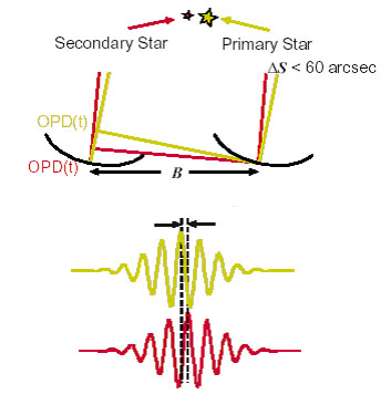
Indeed, the optical path difference (OPD) for the bright object is:
![]()
For the faint one:
![]()
where:
- B is the baseline
- α is the vector pointing to the primary object
- β the vector pointing to the secondary object
- Φi is the intrinsic phase of the bright star
- Ai is caused by the atmospheric turbulences
- Li is the internal optical path difference.
for i = 1,2
Thus the difference between the two OPDs is (cf fig.2):
![]()
where
- ΔS = α - β is the angular separation of the objects. Since ΔS remains constant over several observations with different baselines, it can be determined and substracted
- ΔL = L1- L2 is the optical path difference inside the interferometer due to slightly different paths between the bright and the faint object. It can be measured by the laser metrology system (PRIMET).
- ΔA = A1- A2 is the optical path difference due to the atmospheric turbulence and anisoplanetism causing the random differential motion of the fringe pattern. It introduces an rms error that is proportionnal to 1/ t0.5 (where t is the observing time). For t long enough the average ΔA converges to zero.
- Φ = Φ2 is the phase difference of the faint object with respect to the bright object, considering the phase of the visibility function of the bright object (Φ1) to be zero. It is a phase factor inherent to the nature of the observed objects and is the observable for phased-referenced imaging. Φ is measured several times (together with the contrast of the fringe pattern) using different baselines in order to reconstruct the faint object image.
Micro-arcsecond Astrometry
The high accuracy metrology and the astrometric camera of PRIMA will also allow the measurement of the relative angular positions of stars with a 10 µas accuracy. Detection of Jupiter like planets as far as 240 pc and characterization of gravitational micro-lensing events on the galactic center and on the Magellanic Clouds will then be possible.
In a general way, in an astrometric measurement both object phases (Φ1 and Φ2) are supposed to be zero since a symmetrical intensity distribution is assumed for both objects. As in Imaging mode, ΔA can be considered to be zero for an observing time that is long enough. Therefore the difference of the white light fringe positions together with the measured ΔL gives the exact angular separation of the two objects.
The PRIMA astrometric mode will allow observing simultaneously two fields separated by 2 to 60 arcsec, to detect and track the fringes on the brightest object, to detect the fringes on the faintest, and to measure the phase of the secondary set of fringes relative to the primary one. The differential delay is measured with a very high accuracy (5nm rms) and is related to the angle between the two observed stars. The 200 m baseline would give a figure of merit of 10 µas for a 10'' separation angle, in only 30 min integration time (atmospheric anisoplanetism limit).