
Imaging Mode Characteristics
VIMOS Imaging field orientation
The field of view in imaging mode consists in 4 quadrants of 7' x 8' each, separated by a cross 2' wide. Note that there is some slight vignetting on 2 corners along the 8' direction. The CCD size in imaging mode is 2048x2440 with a pixel size of 0.205 arc seconds.
The field orientation is presented in the following image.
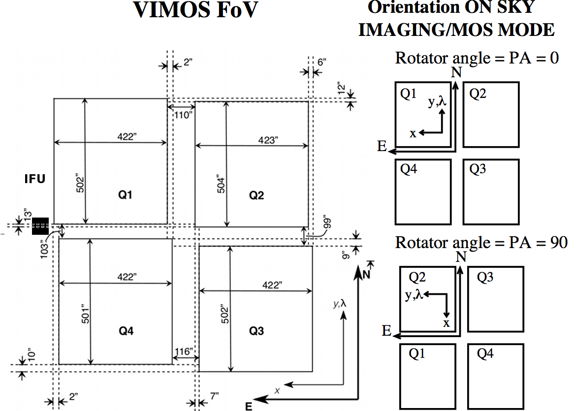
Layout of the VIMOS imaging field of view.
The dispersion direction is horizontal. Click on image for full view.
VIMOS Imaging filters
Imaging with VIMOS is offered with a set of 6 broad band filters. Each arm of VIMOS is equipped with its own set of filters and some minor difference may exist in the transmission curve of the 4 quadrants.
The filters are close to the Mould definition and allow to minimize color term to transform to the Johnson system.
The following table gives the list of VIMOS imaging filters and their properties measured from the observations of spectrophotometric standard stars observed between 21 March and 24 August 2006. The details of the measurements can be found in this document. Notice that the low U filter transmission measured in quadrant 3 is probably an artifact introduced by instrument flexures or incorrect values assumed for grism transmission in Q3. It is recommended that these curves be re-scaled to the (integrated) photometric zero points, found in this page.
List of imaging filters offered for VIMOS
| Filter name | Band pass graph |
| U only, B only, U bandpass, B bandpass | ![[Click here to download ps file]](/sci/facilities/paranal/instruments/vimos/inst/filters_2007-04-04/bandpass_UB.gif) |
| V only, R only, I only V bandpass, R bandpass, I bandpass | ![[Click here to download ps file]](/sci/facilities/paranal/instruments/vimos/inst/filters_2007-04-04/bandpass_VRI.gif) |
| z only, z bandpass | ![[Click here to download ps file]](/sci/facilities/paranal/instruments/vimos/inst/filters_2007-04-04/bandpass_z.gif) |
For the old filter data see this old web page.