The VLTI Control System (VLTICS)
Introduction
During an interferometric observation the successful coordination of all the complex and heterogeneous devices of the VLT Interferometer (VLTI) depends on the effectiveness and reliability of the control system, which carries out the ultimate system integration.
The VLTI Control System (VLTICS) is designed to satisfy both specific technical requirements and general operational constraints.The VLTICS architecture is multi-platform, distributed and network-based. Local Control Units (LCU) consisting of a VME backplane equipped with Central Processing Units (CPUs) and interface boards. The high-level coordinating and monitoring tasks as well as the graphical user interface are run by various Workstations (WS). Ethernet and ATM provide the communication layer among the computing nodes. A Time Bus conveys the Universal Time Coordinated (UTC) which is distributed by a GPS-based Time Reference System (TRS). The control software is constituted by different processes which interact by exchanging commands and replies and share a common on-line database.
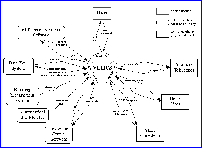
The VLTICS provides the functions to control all the heterogeneous devices belonging to the VLTI. The following table shows the VLTI main elements to be controlled, either directly or indirectly,and the external interfaces:
Direct Control Indirect Control |
Indirect Control |
External Interfaces |
|---|---|---|
|
|
|
The following figure shows the VLTICS inserted in its operational environment.

